The advent of chiplets • Articles • Zest of knowledge, chiplet design kits for 3D ic heterogeneous integration | Siemens Software
Using chiplet design kits to help pave the way for 3D ic heterogeneous integration
A few years later, the first processors appeared with in particular the Intel 4004, relatively simple today. Then the processors became more complex.
The advent of chiplets
Following a discussion in JZDS and on the discord, I told myself that writing an article on the chiplets would be beneficial to the greatest number. And would keep a written track contrary to what can happen to the JZDS
Rather than writing a very long ticket, I preferred the format of the article to get a little more into the details. I hope to be able to teach you what the chiplets are, why this technology was created and why it will develop in the years to come.
- Preamble
- Chiplet, quésaco ?
- Economic aspects of chiplets
- Two examples: AMD and Intel (Altera)
Preamble
This article talks about computer, electronic and architecture concepts of computers which can be advanced enough for certain readers. I offer you a little popularization in this preamble to understand a little better what we are talking about.
For purists, shortcuts will be made, this popularization may be able to contain voluntarily imprecise information to facilitate understanding.
Chiplet, quésaco ?
Let’s start with the most difficult, define what a chiplet is !
Indeed the term chiplet appeared in the 1970s but its use has mainly taken off in recent years, for those who are interested in complex processors or electronic chips such as FPGA (chips whose internal logical doors can be reprogrammed). For the others, at the bottom of the room, you may have never heard of this term, we will remedy it !
Let’s go back to the basis of what an electronic chip is: a piece of engraved silicon (the famous transistors) which is encapsulated in a case. With the crossing components, tiny gold or silver threads connect the legs of the component to the piece of silicon. At the beginning, the chips are made up of transistors engraved with fairly coarse resolutions (compared to today) and the functions were quite basic: logical doors, operational amplifiers, etc. However, it was already enormous progress in terms of miniaturization !
At that time the components had crossing legs and it is necessary to connect the silicon chip to these legs. It is made with thin sons of silver or gold that are welded between the chip and the legs inside the case.
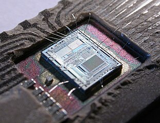
A few years later, the first processors appeared with in particular the Intel 4004, relatively simple today. Then the processors became more complex.
From the 1970s, IBM developed MCM components (Multi-chodu) including several silicon chips in a single case. But this technology will mainly develop in the late 90s. We can note the Pentium Pro of Intel released in 1995. This processor included two silicon chips: one for the processor strictly speaking and another for L2 cache memory (a buffer memory between the processor and the RAM, much faster but much more expensive because engraved with the processor).

As we can see in the photo, the two chips have roughly the same size and Intel offered several sizes of cache L2. The advantage of separating the cache memory processor was to be able to save scale on the processor chip while offering different cache memory sizes by putting a different size chip in the case.
This type of component remains relatively underdeveloped, even if IBM continued to develop MCM components. Note the Power5 of IBM released in 2004 which sees four processors squarely with a cache L3 memory chip. The interconnection of fleas is done inside the case.
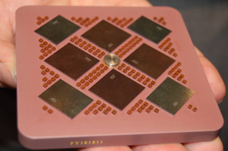
Today the technology has evolved and the MCM chips are present in consumer products with AMD processors. Here we can see an Epyc 7702 processor (released in August 2019) composed of 9 interconnected silicon chips: 8 chips containing cores and cache memory and a central chip connecting the other 8 and which manages the DDR as well as the signals D ‘Entrance/exit (SATA, PCI Express, USB, etc.)).

But tell me Jamy, what is a chiplet ?
Ah yes, I derived a little
In fact a chiplet is one of the silicon chips present in an MCM. A chiplet is made to be interconnected with other chiplets. Yes it’s relatively simple but you had to show some nice photos to understand
Nevertheless to be a little more precise on the meaning of the chiplets, the idea is not necessarily to put several different chips linked together. There is also a notion of generic chip that can be reused and not dedicated to a particular processor reference.
Economic aspects of chiplets
After this introduction while image, let us now understand why the chiplets will develop in the future. To do this, it is necessary to return to the process of manufacturing electronic fleas.
Sit comfortably in an armchair because the trip from the sandy beach will be long
No, wait !
We will spend a whole part of the manufacturing of silicon. What will interest us is the distribution of fleas (die) on the silicon cake (wafer) and in particular the evolution of yield with the increase in engraving finesse.
But before this aspect of the yield, we must talk about the maximum physical size of a die. Indeed, on a silicon pancake the same design of a chip is repeated several times (tens or even hundred times). The impression of this design is done optically via ultraviolet light. However there is a whole set of lenses and optical mechanisms which prevents engraving a single die on the entire silicon cake.
The more we complicate the fleas, the more we want to put transistors, so we must either increase the size of the chip, or increase the delicacy of engraving to fit more transistors in the same surface. But there too other constraints and limits are felt.
This is why the principle of chiplet is interesting to bypass these limits: use several small silicum chips connected together to make a more complex chip but impossible to engrave in a monolithic way.
Now back to the yield (yield in English). First, the wafers are round in shape and we want to engrave it with rectangular chips. The entire silicon is not used. But the smaller the dies at the edges and the more we can have whole dies. It is the same principle as aliasing in a video game: the more the pixels used to form a round shape are small and the less we realize the nicking.
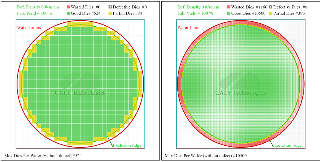
In the example above, if we report the partial dies on the total number of dies (good and bias) we obtain a ratio of 13.8 % in the case of DIES of 5 × 5 mm and 3.6 % in the case of 1 × 1 mm dies. The smaller the die, the more valid dies can have on the edges, which increases the yield.
You can also make a large Die mixture in the center of the wafer and use smaller dies at the edges to optimize the yield due to aliasing.
Say Jamy, why do we use round wafers to make rectangular fleas ?
Well it is because of the method of making silicon called Czochralski process which gives silicon in the form of cylinders, cut into very fine slices to give wafers.
Second, the yield is affected by the defects that may appear on the WAFER. You can think of dust grains that fall on the wafer.
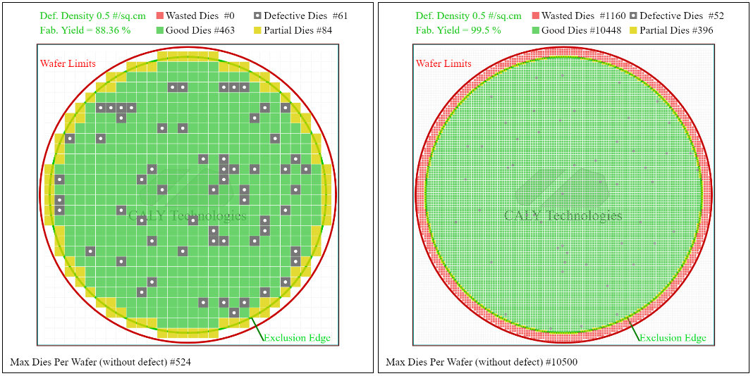
I resumed the previous example by adding a fault density of 0.5 per cm². Now compare the Yield manufacturing which corresponds to the ratio between the number of functional dies and the total number of products produced. In the case of a 5 × 5 mm die, the yield is 88.4 % while with 1 × 1 mm dies, the yield is 99.5 %.
It is therefore doubly interesting to have small dies to optimize the production of electronic fleas. Nevertheless, cutting a complex chip into several smaller chips requires communicating these different chips between them, we must therefore add communication elements that come to take up additional space and use additional energy.
In addition, the use of chiplets can make it possible to use dies of different finesse of engraving according to the functions allowing to modulate the costs of the final chip with the performance.
Finally, another economic aspect to see is the complexity of developing new features. This tends to have specialized companies (or at least start-ups at the start) offering intellectual property blocks (functions) ready to use. For example, a processor manufacturer will be able to focus on the development of the processor itself while buying DIES for functions such as PCI Express, USB or DDR controllers.
To facilitate the interoperability of chiplets coming from different manufacturers, major players like Intel, AMD, ARM, Qualcomm, Samsung or TSMC have created a communication standard between Chipplets, UCIE (Universal Chiplet Interconnect Express)).
Two examples: AMD and Intel (Altera)
AMD Epyc
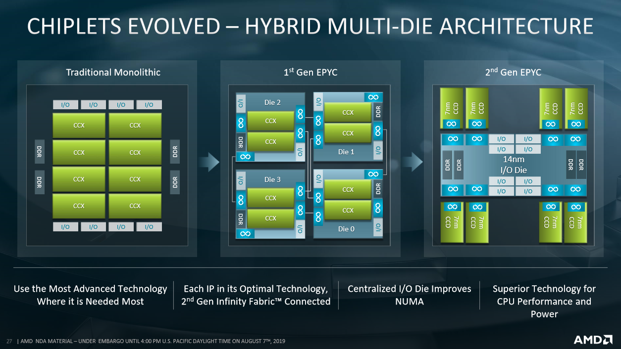
Today more and more processors use this chiplets technique. AMD uses chiplets since the first generation of Epyc processors, where the different hearts are linked together by theInfinity Fabric.
The first generation of Epyc processors saw a set of Dies that could be equated with complete processors being linked together by theInfinity Fabric To form the final processor. The chiplets were therefore a kind of small autonomous processor: each die managed its entries/outputs and had its DDR controller.
These dies, or rather chiplets, have two Core Compute Complex (CCX, a set of four cores with cache memory) as well as a DDR controller, manages inputs/outputs (PCI Express for example) and has communication modules for theInfinity Fabric.
Small subtlety, there are always four chiplets on a first generation Epyc. To vary the number of hearts, AMD deactivates hearts inside CCX. For example to have 24 cores, CCX have only 3 active cores
This first generation therefore used the principle of chiplets as a kind of copy/glued of Dies instead of developing a large monolithic die.
For the second generation, AMD pushes the concept a little further. Indeed, the CCXs are now independent, grouped in pairs within a Core Compute Die (CCD) connected by Infinity Fabric to a die managing the DDR and the entries/exits called I/o die (Iod).
AMD fully exploits this increased separation from functions. Indeed the CCD is engraved in 7 nm while the iod is engraved in 14 nm.
Below an AMD presentation summarizing the passage in chiplets of the Epyc processors.
Intel FPGA (Altera)
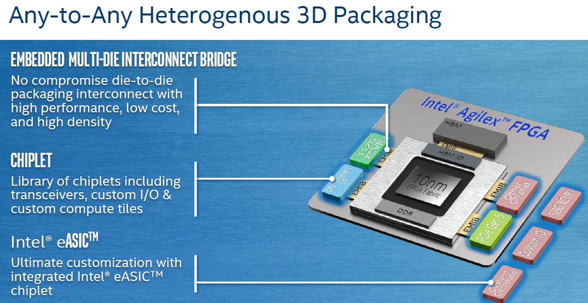
Intel processors are always monolithic chips except a few exceptions as we could see at the start of this article. Nevertheless in the Intel FPGA (Reconfigurable Fpga) sector uses chiplets for the latest generation, Agilex.
These chiplets mainly concern the type of transcense used (fast links) and are called Tiles. If Intel offers predefined ranges from these tiles, it must be possible to have customized chips for your own needs.
The tiles are divided by maximum speed of transceivers and the protocols supported (Ethernet, PCI Express, etc.): 16g for P, 28g for H, 32g for R, etc.
Intel also evokes for the future the possibility of connecting customized chiplets that would provide additional functions. Currently companies have released an ADC/DAC (Jariett Technologies) chiplet as well as another optical connection (Ayar Labs).
Finally we must not believe either that the chips monolithic are dead. They always have advantages, especially in terms of internal communication and latency, which can be critical for certain applications requiring large -sized chips.
This is the case of Broadcom and its Switch 400g chips whose choice is explained by the designer in this video: https: // www.Youtube.Com/Watch?V = B-Cogmbaug4
I hope this article has more to you and allowed you to know a little more about the manufacture of current chips. I tried to popularize a complex subject, I also hope I was able to keep you after the first paragraph
Do not hesitate to leave a comment if certain points remain cryptic for you, I will try to provide details.
6 comments

This answer was useful
Excellent article, thank you @ zeql !
“Throw me to the wolves and I will return the pack.” – Seneca
This answer was useful
I was wondering how much the advent of the chiplets was able to consider a certain evolution in hardware (as well consumer-grade that server-grade) in the future, or even a paradigm shift on the way that we design highly and optimal machines overall.
Certain well integrated systems (especially at Apple) are not based solely on a very efficient “classic” CPU, but also on several specialized auxiliary chips which unload generalist CPUs. In a limited system as a smartphone, we can find H265 transcoding chips, calculation units for AI (Apple Neural Engine) and of course the classic graphic unit.
I therefore take up the diagram of AMD Epyc of 2nd generation and I wonder if the chiplets would be a simple way to produce commercially and industrially viable from the complete units which embark several specialized chips to achieve optimal performance on certain tasks. For example, a unit could provide for classic CCDs, but also a DSP, a GPU, Transco H265/AV1/VP9/…, a chip to do AES, etc. and connect it all through iod/infinity manufacture. Each manufacturer of machines/servers could therefore compose its ready-to-use final unit by having composed itself and without R&D/Faramineurous industrialization costs.
It reminds me of the concept of apu, but I don’t know if there is a report.
So you should know that a chip is often done with IP (Intellectual Property): a function sold quite ready at the “transistors” level but that must be integrated into its design.
A classic example is a DDR3 controller on on -board microcontroller. The manufacturer of the microcontroller does not necessarily master the DDR3 and does not have the skills, the time (neither the desire) to create a DDR3 controller. He therefore buys an IP from a controller and integrates him into his design.
You have to succeed in seeing the difference between the possibility of an IP and a chiplet. For me the chiplet is there to come and bring one or more advanced features and which have already passed the tests of the engraving, therefore an additional step in the design. But there remains the problem of testing the full soil with all the chiplets. So we cannot create hundreds of variations like a Lego. It takes a minimum of economic reality.
But yes, for a certain volume we can create à la carte sockets.
The big advantage is on the production side of the chip: if an IP can be declined for different engraving finesse, a chiplet to the advantage of being able to always be engraved in its initial finesse (if it is sufficient) when other parts chip can be improved with smaller engraving.
This answer was useful
Besides I thought that the chiplets could be used in a modular design. You take a design with 4 chips, the fleas with faults are distributed throughout the production, and those with 3 chips that work on 4 will be a range below and a little cheaper than those with the 4 that work.
Which simplifies design and industrialization in relation to conventional operation.
Lover of free software and GNU/Linux Fedora distribution. #Jesuisarius
This answer was useful
Thank you for this interesting mega article. I would love you too much time to detail each point that you do not explain in tutorial to really understand things but interesting anyway .
Using chiplet design kits to help pave the way for 3D ic heterogeneous integration

A chiplet is an asic die specificly designed and optimized for operation within a package in conjunction with other chiplets. Heterogeneous Integrated (HI) Involves Integant Multiple Die or Chiplets Into System-In-Package (SIP) Chipplets. These devices offered to be considable Benefits, included performance, Power, Area, Cost and TTM.
The Chiplet Design Exchange (CDX) Consists of Eda Vendors, Chiplet
Providers/Assemblers and SIP Integrators and is an open working group to recommend standardized chiplet models and workflows to facilitate a chiplet ecosystem. This Webinar Summarizes The Chiplet Design Kits (CDKS) offers to help standardize 2.5D and 3.D ic designs to create an open ecosystem.
Building an ecosystem for successful 2.5D and 3D Chiplet Model Integration
Similar to an Soc Process, you need an ecosystem for chipplets. Key Enables for General Market Adoption and Deployment of Chiplet Based Designs Included:
- Technology: 2.5 d interposition and 3D stacked die manufacturing and assembly processes
- IP: Standardized Chiplet Models
- Workflows: EDA Design Flows and PDK, CDK, DRM & Assembly Rules
- Business Models: Chiplet Marketplace
The initial focus of the cdx is 2.5d interposing-based chiplet models with 3D to follow. Learn More about these efforts in the webinar.
The Chiplet Design Exchange (CDX) Consists of Eda Vendors, Chiplet Providers/Assemblers and SIP Integrators and is an Open Working Group to Recommend Standardized Chiplet Models and Workflows to Facilitate A Chiplet Ecosystem. This Webinar Summarizes The Chiplet Design Kits (CDKS) offers to help standardize 2.5D and 3.D ic designs to create an open ecosystem.
Building an ecosystem for successful 2.5D and 3D Chiplet Model Integration
Similar to an Soc Process, you need an ecosystem for chipplets. Key Enables for General Market Adoption and Deployment of Chiplet Based Designs Included:
- Technology: 2.5 d interposition and 3D stacked die manufacturing and assembly processes
- IP: Standardized Chiplet Models
- Workflows: EDA Design Flows and PDK, CDK, DRM & Assembly Rules
- Business Models: Chiplet Marketplace
The initial focus of the cdx is 2.5d interposing-based chiplet models with 3D to follow. Learn More about these efforts in the webinar.
Leaked image reveals an ambitious design of chiplet for the GPU Amd Radeon
Leaked image reveals an ambitious design of chiplet for the GPU Amd Radeon
- by
- In News
- on August 16, 2023

A leaked image has surfaced, revealing a GPU design with radeon chiplets, supposedly from a canceled project of the Navi 4C chip 4C. The design present between 13 and 20 different chiplets on a single GPU, testifying to the ambitious AMD approach. This more complex chiplet design differs from the Navi 31 silicon currently used in the Radeon RX 7900 XTX. While the previous iteration of the GPU was considered a first generation, it did not use a real chiplet design like the recent Ryzen processors of AMD. However, the conception of Navi 4C disclosed represents a significant advance, because it incorporates several calculation chiplets, as well as distinct I/O chiplets, on a single substrate. The leaked image presents 13 chiplets, with the possibility of additional memory controller chips not displayed on the image.
To confirm the authenticity of the image, a relevant patent of 2021 discussing the concept of modularity in parallel processors is highlighted. The patent patterns closely resemble the design shown in the leaked image, even suggesting the possibility of more chiplets on the other side of the transverse cup.
Unfortunately, the design of the GPU presented in the leaked image has been canceled. This agrees with recent relationships suggesting that AMD’s accent for the next generation of GPU will be on the Navi 43 and Navi 44 monolithic chips intended for the general public, rather than on high -end components. However, it is speculated that AMD redirects its efforts to the development of a GPU composed of several calculation chiplets for the high -end segment of its future range of graphics cards, potentially with RDNA 5.
Although the realization of several calculation chiplets for game graphics is more complex than for traditional CPU calculations, AMD’s decision to overcome design obstacles now and work on a better solution for RDNA 5 is perceived as a positive step. It would have been advantageous for AMD to have a rescue plan, such as a new node for an improved version of Navi 31.


