


Configuration of a basic MPL VPN network – Cisco, IP/MPLS networks by Yazid Karkab
![]()
IP/MPLS networks
Perform these steps on the PE after the configuration of MPLS (configuration of Mpls IP Oon interfaces).
Configuration of a basic MPL VPN network
As part of the documentation associated with this product, we strive to use a language free of prejudices. In this set of documents, the language free of discrimination refers to a language which excludes discrimination according to age, handicaps, gender, racial belonging to ethnic identity, sexual orientation, the socio-economic situation and the intersectionality. Exceptions may apply in documents if the language is coded in hard in user interfaces of the software product, if the language used is based on RFP documentation or if the language used comes from a third -party product referenced. Find out how Cisco uses inclusive language.
About this translation
Cisco has translated this document into automated translation verified by a person as part of a global service allowing our users to obtain assistance content in their own language. However, it should be noted that even the best automated translation will not be as precise as that provided by a professional translator.
Contents
Introduction
This document describes how to configure a basic VPN MPLS network (Multiprotocol Label Switching).
Preconditions
Requirements
No specific requirements are associated with this document.
Components used
The information contained in this document is based on the following hardware and software versions:
- P and PE routers
- Version of the IOS® Cisco software which includes the MPLS VPN functionality.
- Any Cisco router in the 7200 or posterior range supports the P functionality.
- The Cisco 2600, as well as any router in the 3600 or posterior range support the PE functionality.
- You can use any router that can exchange routing information with its PE router.
The Information in this Document was created from the devices in a specific lab environment. All of the Devices used in this document started with a cleared (default) configuration. If your network is online, be sure to understand the possible impact of orders.
Related products
To apply the MPLS functionality, you must have a router from the Cisco 2600 or posterior range. To select the Cisco iOS with MPLS functionality required, use the Software Research tool. Also check the RAM and the additional flash memory necessary to perform the MPLS functionality in the routers. WIC-1T, WIC-2T and standard interfaces can be used.
Conventions
For more information on the conventions used in this document, see conventions relating to Cisco technical advice.
These letters represent the different types of routers and switches used:
- P – Supplier’s main router.
- PE – Supplier periphery router.
- THIS – Customer periphery router.
- VS – Customer router.
Noticed : PE routers are the last jump in the supplier network and it is the peripherals that connect directly to the routers which do not know the MPLS functionality, as illustrated in the following diagram.
This scheme presents a standard configuration illustrating the conventions described above.
Typical MPLS VPN network diagram
General informations
This document provides an example of configuration of an MPLS VPN (Multiprotocol Label Switching) when the BGP (Border Gateway Protocol) protocol is present on Cisco customers sites.
Used with MPLS, VPN functionality allows multiple sites to interconnect transparent via a service provider network. A network of the service provider can support several different IP VPNs. Each of the latter appears to its users as a private network, separated from all other networks. In a VPN, each site can send IP packets to any other site in the same VPN.
Each VPN is associated with one or more VRF (Virtual Routing and Forwarding) instances). A VRF consists of an IP routing table, a table derived from Cisco Express Forwarding (CEF) and a set of interfaces that use this reaches table. The router manages a routing information base (RIB) and a separate CEF table for each VRF. Therefore, the information is not sent outside the VPN and makes it possible to use the same subnet in several VPNs and do not cause IP address problems. The router that uses the BGP Multiprotocol (MP-BGP) protocol distributes VPN routing information to extensive MP-BGP communities.
Configuration
This section provides configuration examples and explains how they are implemented.
Network diagram
This document uses the following network configuration:
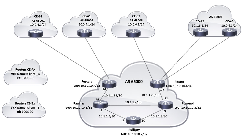
Topology
Configuration procedures
MPLS configuration
1. Check that IP Cef is activated on the routers where MPLS is required. To improve performance, use IP CEF Distributed (if applicable).
2. Configure an IGP protocol on the heart of the service provider, the OSPF (Open Shortet Path First) or IS-IS (Intermediate System-To-Intermediate System) protocols being the recommended options, and announce the LoopBack0 from each IP router and PE.
3. Once the main service provider routers are fully accessible to layer 3 between their loops, configure the command MPLS IP On each L3 interface between the P and PE routers.
Noticed : the interface of the PE router which connects directly to the router this does not require MPLS IP Command configuration.
Perform these steps on the PE after the configuration of MPLS (configuration of Mpls IP Oon interfaces).
- Create a VRF for each VPN connected to the VRF Definition Erasecat4000_flash:. Additional steps: Specify the road marker used for this VPN. The command RD is used to extend the IP address so that you can identify which VPN it belongs.
VRF Customer Definition_A RD 100: 110
Configure import and export properties for extensive MP-BGP communities. They are used to filter the import and export process with the road-target command as indicated in the following result:
VRF Definition Customer_A RD 100: 110 Route-Target Export 100: 1000 Route-Target Import 100: 1000 ! Address-Family IPV4 Exit-Address-Family
Pescara#show run interface gigabitethernet0/1 Building Configuration. Current Configuration: 138 bytes ! Gigabitethernet0/1 VRF Forwarding Customer_A IP IP Address 10 interface.0.4.2,255.255.255.0 Duplex Auto Speed Auto Media-Type RJ45 End
MP-BGP configuration
There are several ways to configure BGP, for example, you can configure PE routers as BGP neighbors or use a road reflector (RR) or Confederation methods. A road reflector is used in the following example, which is more scalable than the use of direct neighbors between PE routers:
- Enter the command Address-Family IPV4 VRF For each VPN present on this PE router. Then perform one or more of the following steps, if necessary:
- If you use BGP to exchange routing information with the CE, configure and activate the BGP neighbors with the Routeurs CE.
- If you use another dynamic routing protocol to exchange routing information with the CE, redistribute routing protocols.
Noticed : Depending on the routing protocol you use, you can configure any dynamic routing protocol (EIGRP, OSPF or BGP) between the PE and this peripherals. If BGP is the protocol used to exchange routing information between PE and CE, it is not necessary to configure redistribution between protocols.
2. Enter it Address-Family VPNV4 And perform the following steps:
- Activate the neighbors, a VPNV4 neighborhood session must be established between each PE router and the road reflector.
- Specify that the extended community should be used. This is compulsory.
Configurations
This document uses these configurations to configure the example of a MPLS VPN network:
HOSTNAME PESCARA ! IP Cef ! !--- VPN customer_a commands. VRF Definition Customer_A RD 100: 110 Route-Target Export 100: 1000 Route-Target Import 100: 1000
! Address-Family IPV4 Exit-Address-Family
!--- Enables The VPN Routing and Forwarding (VRF) Routing Table.
!--- Distinguisher Creats Routing and Forwarding Route Tables for a VRF.
!--- Route Targets Creates Lists of Import and Export Extended Communities for the specific vrf.
!--- VPN customer_b commands.
VRF Customer Definition_B RD 100: 120 Route-Target Export 100: 2000 Route-Target Import 100: 2000 ! Address-Family IPV4 Exit-Address-Family
!
LOOPBACK0 IP Address 10 interface.10.10.4 255.255.255.255 IP Router Isis
! Gigabitethernet0/1 VRF Forwarding Customer_A IP IP Address 10 interface.0.4.2,255.255.255.0 Duplex Auto Speed Auto Media-Type RJ45 ! Gigabitethernet0/2 VRF Forwarding Customer_B IP Address 10 interface.0.4.2,255.255.255.0 Duplex Auto Speed Auto Media-Type RJ45
!--- Associates A VRF Instance with an interface or subinterface.
!--- Gigabitethernet0/1 and 0/2 use the Same IP Address, 10.0.4.2.
!--- This is allowed because they Belong to Two Different Customer Vrfs.
!
Gigabitethernet0/0 Interface Link to Pauillac IP Address 10.1.1.14 255.255.255.252 IP Router Isis Duplex Auto Speed Auto Media-Type RJ45 MPLS IP
!--- MPLS on the L3 Interface Connecting to the P Router
!
Router Isis Net 49.0001.0000.0000.0004.00 IS-Type Level-2-Only Metric-Style Wide Passive-Interface Loopback0
!--- IS-IS AS THE IGP in the Provider Core Network
! Router BGP 65000 BG LOG-Neighbor-Changes
Neighbor 10.10.10.2 Remote-as 65000
Neighbor 10.10.10.2 Update-Source loopback0
!--- Adds an Entry to the BGP or Mp-Bgp Neighbor Table.
!--- And enables bgp sessions to use a specific operational interface for TCP connections.
! Address-Family VPNV4 Neighbor 10.10.10.2 NEIGHBOR ACTIVATE 10.10.10.2 Send-Community Both Exit-Address-Family
!--- To enter Address Family Configuration Mode that use standard VPN version 4 Address Prefixes.
!--- CREATES THE VPNV4 NEIGHBOR Session to the Route Reflector.
!--- And to send the community attribute to the bgp neighbor.
! Address-Family IPV4 VRF Customer_a Neighbor 10.0.4.1 Remote-as 65002 Neighbor 10.0.4.1 Exit-Address-Family Activate ! Address-Family IPV4 VRF Customer_b Neighbor 10.0.4.1 Remote-as 65001 Neighbor 10.0.4.1 Exit-Address-Family Activate
!--- These are the ebgp sessions to each this router Belinging to Different Customers.
!--- The EBGP sessions are configured with the vrf address family
!
endingHostname Pesaro ! IP Cef
! VRF Definition Customer_A RD 100: 110 Route-Target Export 100: 1000 Route-Target Import 100: 1000 ! Address-Family IPV4 Exit-Address-Family !
VRF Customer Definition_B RD 100: 120 Route-Target Export 100: 2000 Route-Target Import 100: 2000 ! Address-Family IPV4 Exit-Address-Family ! IP Cef ! LOOPBACK0 IP Address 10 interface.10.10.6 255.255.255.255
IP Router Isis
! Gigabitethernet0/0 Description Link to Pomerol IP Address 10.1.1.22 255.255.255.252 IP Router Isis Duplex Auto Speed Auto Media-Type RJ45 MPLS IP ! Gigabitethernet0/1 VRF Forwarding Customer_B IP Address 10 interface.0.6.2,255.255.255.0 Duplex Auto Speed Auto Media-Type RJ45 ! Gigabitethernet0/2 VRF Forwarding Customer_A IP IP Address 10 interface.1.6.2,255.255.255.0 Duplex Auto Speed Auto Media-Type RJ45 ! Gigabitethernet0/3 VRF Forwarding Customer_A IP IP Address 10 interface.0.6.2,255.255.255.0 Duplex Auto Speed Auto Media-Type RJ45 ! Router Isis Net 49.0001.0000.0000.0006.00 IS-Type Level-2-Only Metric-Style Wide Passive-Interface Loopback0 ! Router BGP 65000 Bgp Log-Neighbor-Changes Neighbor 10.10.10.2 Remote-as 65000 Neighbor 10.10.10.2 Update-Source loopback0 ! Address-Family VPNV4 Neighbor 10.10.10.2 NEIGHBOR ACTIVATE 10.10.10.2 Send-Community Both Exit-Address-Family ! Address-Family IPV4 VRF Customer_a Neighbor 10.0.6.1 Remote-as 65004 NEIGHBOR 10.0.6.1 NEIGHBOR ACTIVATE 10.1.6.1 Remote-as 65004 NEIGHBOR 10.1.6.1 Exit-Address-Family Activate ! Address-Family IPV4 VRF Customer_b Neighbor 10.0.6.1 Remote-as 65003 Neighbor 10.0.6.1 Exit-Address-Family Activate ! ! endingHostname Pomerol ! IP Cef ! LOOPBACK0 IP Address 10 interface.10.10.3 255.255.255.255 IP Router Isis ! Gigabitethernet0/0 Description Link to Pesaro IP Address 10.1.1.21 255.255.255.252 IP Router Isis Duplex Auto Speed Auto Media-Type RJ45 MPLS IP ! Gigabitethernet0/1 interface Link to Pauillac IP Address 10.1.1.6 255.255.255.252 IP Router Isis Duplex Auto Speed Auto Media-Type RJ45 MPLS IP ! Gigabitethernet0/2 interface Link to pouligny ip address 10 description.1.1.9 255.255.255.252 IP Router Isis Duplex Auto Speed Auto Media-Type RJ45 MPLS IP ! Router Isis Net 49.0001.0000.0000.0003.00 IS-Type Level-2-Only Metric-Style Wide Passive-Interface Loopback0 ! ending
HOSTNAME PULLIGNY ! IP Cef ! LOOPBACK0 IP Address 10 interface.10.10.2,255.255.255.255 IP Router Isis ! Gigabitethernet0/0 Interface Link to Pauillac IP Address 10.1.1.2,255.255.255.252ip Router Isis Duplex Auto Speed Auto Media-Type RJ45 Mpls IP ! Gigabitethernet0/1 Link to Pomerol IP Address 10 description.1.1.10 255.255.255.252ip Router Isis Duplex Auto Speed Auto Media-Type RJ45 Mpls IP ! Interface Gigabitethernet0/3 No IP Address Shutdown Duplex Auto Speed Auto Media-Type RJ45 ! Router Isis Net 49.0001.0000.0000.0002.00 IS-Type Level-2-Only Metric-Style Wide Passive-Interface Loopback0 ! Router BGP 65000 Bgp Log-Neighbor-Changes Neighbor 10.10.10.4 Remote-as 65000 Neighbor 10.10.10.4 Update-Source LoopBack0 Neighbor 10.10.10.6 Remote-as 65000 Neighbor 10.10.10.6 Update-Source Loopback0 ! Address-Family VPNV4 Neighbor 10.10.10.4 NEIGHBOR ACTIVATE 10.10.10.4 Send-Community Both Neighbor 10.10.10.4 route-reflector-client Neighbor 10.10.10.6 NEIGHBOR ACTIVATE 10.10.10.6 Send-Community Both Neighbor 10.10.10.6 Route-Reflector-Client Exit-Address-Family ! ! ending
Hostname Pauillac ! IP Cef ! LOOPBACK0 IP Address 10 interface.10.10.1,255.255.255.255 IP Router Isis ! Gigabitethernet0/0 Interface Link to Pescara IP Address 10 description.1.1.13 255.255.255.252 IP Router Isis Duplex Auto Speed Auto Media-Type RJ45 MPLS IP ! Gigabitethernet0/1 Link to Pulligny IP Address 10 description.1.1.5 255.255.255.252 IP Router Isis Duplex Auto Speed Auto Media-Type RJ45 MPLS IP ! Gigabitethernet0/2 Interface Link to Pomerol IP Address 10 Description.1.1.1,255.255.255.252 IP Router Isis Duplex Auto Speed Auto Media-Type RJ45 MPLS IP ! Router Isis Net 49.0001.0000.0000.0001.00 IS-Type Level-2-Only Metric-Style Wide Passive-Interface Loopback0 ! ending
HOSTNAME CE-A1 ! IP Cef ! Gigabitethernet0/0 IP Address 10 interface.0.4.1,255.255.255.0 Duplex Auto Speed Auto Media-Type RJ45 ! Router BGP 65002 BGP Log-Neighbor-Changes Redistribute Connected Neighbor 10.0.4.2 Remote-as 65000 ! ending
HOSTNAME CE-A3 ! IP Cef ! Gigabitethernet0/0 IP Address 10 interface.0.6.1,255.255.255.0 Duplex Auto Speed Auto Media-Type RJ45 ! Router BGP 65004 BGP Log-Neighbor-Changes Redistribute Connected Neighbor 10.0.6.2 Remote-as 65000 ! ending
Verification
This section provides information that you can use to confirm that the configuration is working properly:
PE verification commands to this
- Show IP VRF – Check that the correct VRF exists.
- Show IP VRF Interfaces – Check the activated interfaces.
- Show IP Route VRF: Check routing information on PE routers.
- VRF tracer – Check routing information on PE routers.
- Show IP Cef VRF Detail – Check routing information on PE routers.
LDP MPLS verification controls
PE/RR verification controls
- VPNV4 Unicast All Summary show BGP
- show bgp vpnv4 unicast all neighbor adverited-red – Check the sending of VPNV4 prefixes
- VPNV4 Unicast All Neighbor Routes show – Check the prefixes VPNV4 received
Here is an example of ordering output of the Show IP VRF command.
Pescara#VRF IP show Name DEFAULT RD Interfaces Customer_A 100: 110 GI0/1 Customer_B 100: 120 GI0/2
Here is an Example of ordering output of the Show IP VRF Interfaces command.
Pesaro#Show IP VRF Interfaces IP-Address VRF Protocol GI0/2 10 interface.1.6.2 client_a up gi0/3 10.0.6.2 client_a up gi0/1 10.0.6.2 client_b up
In this following example, the Show IP Route VRF commands display the same prefix 10.0.6.0/24 in the two outings. Indeed, the distant PE has the same network for two Cisco, CE_B2 and CE_3 customers, which is authorized in a typical VPN MPL solution.
Pescara#Show IP Route VRF Customer_a Routing Table: Customer_a Codes: L - Local, C - Connected, S - Static, R - RIP, M - Mobile, B - BGP D - EIGRP, Ex - Eigrp External, O - OSPF, IA - OSPF Inter Area N1 - OSPF NSSE External Type 1, N2 - OSPF NSS External Type 2 E1 - OSPF External Type 1, E2 - OSPF External Type 2 I - IS -IS, SU - IS -IS Summary, L1 - IS -IS LEVEL -1, L2 - IS -Is Level -2 IA - IS -IS Inter Area, * candidate Default, U - Per -User Static Route O - Odr, P - Periodic Downloaded Static Route, H - NHRP, L - Lisp A - Route + - Replicated Road, % - Next Hop Override, P - Overrides from Pfr Gateway of Last Resort is not set 10.0.0.0/8 IS Variably Subneted, 4 subnets, 2 masks C 10.0.4.0/24 is directly connected, gigabitethernet0/1 L 10.0.4.2/32 is directly connected, gigabitethernet0/1 b 10.0.6.0/24 [200/0] via 10.10.10.6, 11:11:11 b 10.1.6.0/24 [200/0] via 10.10.10.6, 11:24:16 Pescara# pescara#Show IP Route VRF Customer_B Routing Table: Customer_B Codes: L - Local, C - Connected, S - Static, R - RIP, M - Mobile, B - BGP D - EIGRP, Ex - Eigrp External, O - OSPF, IA - OSPF Inter Area N1 - OSPF NSSE External Type 1, N2 - OSPF NSS External Type 2 E1 - OSPF External Type 1, E2 - OSPF External Type 2 I - IS -IS, SU - IS -IS Summary, L1 - IS -IS LEVEL -1, L2 - IS -Is Level -2 IA - IS -IS Inter Area, * candidate Default, U - Per -User Static Route O - Odr, P - Periodic Downloaded Static Route, H - NHRP, L - Lisp A - Route + - Replicated Road, % - Next Hop Override, P - Overrides from Pfr Gateway of Last Resort is not set 10.0.0.0/8 IS Variably SubNetted, 3 Subnets, 2 Masks C 10.0.4.0/24 is directly connected, gigabitethernet0/2 L 10.0.4.2/32 is directly connected, gigabitethernet0/2 b 10.0.6.0/24 [200/0] via 10.10.10.6, 11:26:05
When you run a tracered command between two sites, in this example two customer_a sites (CE-A1 à CE-A3), it is possible to see the stack of labels used by the MPLS network (if it is configured to do it By MPLS IP Propagate-TTL).
CE-A1#Show IP Route 10.0.6.1 Routing Entry for 10.0.6.0/24 KNOWN via "BGP 65002", Distance 20, Metric 0 TAG 65000, External type Last update from 10.0.4.2 11:16:14 AGO Routing Descriptor Blocks: * 10.0.4.2, from 10.0.4.2, 11:16:14 AGO Route Metric is 0, Traffic Share Count is 1 as hops 2 route tag 65000 mpls label: none ce-a1#
CE-A1#Ping 10.0.6.1 Sequence to abort escape type. Sending 5, 100-Byte ICMP Echos to 10.0.6.1, Timeout is 2 seconds: . Success RATE IS 100 DREST (5/5), Round-Trip Min/AVG/MAX = 7/8/9 MS CE-A1#
CE-A1#tracery 10.0.6.1 Probe 1 Numeric Sequence to abort escape type. Tracing the Road to 10.0.6.1 VRF info: (VRF in name/id, vrf out name/id) 1 10.0.4.2 2 MSEC 2 10.1.1.13 [MPLS: LABELS 20/26 Exp 0] 8 MSEC 3 10.1.1.6 [MPLS: LABELS 21/26 Exp 0] 17 MSEC 4 10.0.6.2 [AS 65004] 11 MSEC 5 10.0.6.1 [AS 65004] 8 MSEC
Noticed : EXP 0 is an experimental field used for quality of service (QOS).
The following result shows the IS-IS and LDP contiguity established between the RR router and some of the IP routers of the main service provider:
Pulligny#Show Isis Neighbors Tag NULL: System ID Type interface IP Address State Holdtime Circuit ID Pauillac L2 GI0/0 10.1.1.1 Up 25 Pulligny.01 POMEROL L2 GI0/1 10.1.1.9 Up 23 Pouligny.02 PULLIGNY# PULLIGNY#MPLS LDP Neighbor Peer LDP Ident: 10.10.10.1: 0; LDP Local Ident 10.10.10.2: 0 TCP Connection: 10.10.10.1.646 - 10.10.10.2.46298 State: Oper; MSGS Sent/RCVD: 924/921; DOWNSTREAM UP TIME: 13:16:03 LDP Discovery Sources: Gigabitethernet0/0, SRC IP ADDR: 10.1.1.1 Addresses Bound to Peer LDP IDDER: 10.1.1.13 10.1.1.5 10.1.1.1 10.10.10.1 Peer LDP Ident: 10.10.10.3: 0; LDP Local Ident 10.10.10.2: 0 TCP Connection: 10.10.10.3.14116 - 10.10.10.2.646 State: Oper; MSGS Sent/RCVD: 920/916; DOWNSTREAM UP TIME: 13:13:09 LDP Discovery Sources: Gigabitethernet0/1, SRC IP ADDR: 10.1.1.9 Addresses Bound to Peer LDP Ident: 10.1.1.6 10.1.1.9 10.10.10.3 10.1.1.21
Related information
- Reference of MPLS commands
- Technical assistance and documentation – Cisco Systems
IP/MPLS networks

IP/MPLS networks is based on the path between two machines (the Switched Path or LSP label). The switching of the packages circulating on this path is made by analyzing a label contained in the MPLS header which is added between layer 2 (often Ethernet) and the IP layer.
Here is a scheme summarizing the principle of label switching throughout a path or Switched Path label:
At the entrance to the MPLS network, the IP packages are inserted a label by the “Ingress label Edge Router” or “Ingress LER”. The LERs are the MPLS routers located on the outskirts of the operator’s network. Labelized packages are then switched to the heart of the network according to its label issue. The MPLS Routeurs du Coeur de Network, the Switching Router label, then switches the labels to the exit ler (Egress Ler) the path that was taken by the package, and previously established, through the network is called a label Switched Path (LSP).The diagram shows us the detail of the protocol battery implemented during this transmission, we note the presence of the MPLS label between the Ethernet layer and the IP layer. We will now analyze the format of the MPLS header:

The MPLS header has a size of 4 bytes and is composed by the following fields:
- The label number
- COS: Each labeled package can be awarded a Class of Service, in order to allow different “Politics Discard” or “Scheduling Politics” for packages with the same label issue. However, the RFC specifies that it is a still experienced field.
- S: Bottom of Stack. The bit “S” is 1 when the last label of the battery is reached. We will see later that we can stack the labels (for example to create tunnels).
- TTL: This field has the same role as the TTL of the IP header. Since the IP header is not analyzed by the LSR, the value of the TTL is copied in the MPLS header at the entrance to the network by the Ingress LER. Then, with each switching by an LSR, the TTL is modified. The TTL value of the MPLS header is then copied into the IP header at the exit of the MPLS network by the Egress LER.
We will now see, how is the decision to award a particular label to an IP package. Then we will see how the labels are exchanged between the LSRs, because exchanges are essential to build the LSP and the switches.
Forwarding Equivalent Class
IP packages entering the MPLS network are associated with a FEC: Forwarding Equivalent Class.
A FEC will define how will be sent through all the MPLS network. In IP, the classification of a package in a FEC is made on each router, from the destination IP. In MPLS, the choice of a FEC can be made according to several parameters (IP address source, destination and QOS parameter (debit, delai)).
The parameters involved in the classification of a package in a FEC depends on the label distribution protocol used: LDP or RSVP-TE. Indeed only RSVP-TE, which we will detail later, makes it possible to classify a package in a FEC according to QOS parameters.To classify a package in a FEC, MPLS relies on the routing protocol implemented on the IP network. For example, the LDP protocol associates a FEC by network prefix present in the router routing table. In addition, a FEC can be awarded several “Class of Service”, in order to allow different “Politics Discard” or “Scheduling Politics” (Cos of the MPLS header).
Thus, each FEC is associated with an exit label. The router will therefore know which label he must attribute to the IP packages corresponding to this or that FEC.We will now see how these FEC/Labels associations are distributed between all the routers of the network. Indeed, these exchanges are essential for the establishment of LSP, because each node must know which label it must attribute to a FEC before sending it to its neighbor.
Distribution of labels
In IP/MPLS networks there are two labels distribution modes.

The first distribution mode is the “Unsolicited Downnstream”. Here is a diagram synthesizing its operation:
The principle is simple, as soon as a router associated with a label with a FEC, he informs all his neighbors of this association. And that automatically. This aims to increase traffic due to “signaling” on the network.The second distribution mode, which is the most used in IP/MPLS networks, is called “Downnstream on Demand”.

With this distribution method, the upstream LSR asks the DOWNSTream LSR to provide him with the label number which he associated with a particular FEC. The upstream LSR is the router who sends traffic to the Downnstream LSR, so when the passage of a package is not yet associated with a FEC, the upstream LSR will have to ask for the association of a label for this FEC at the following LSR (the Downnstream LSR on this diagram).
It is this last distribution mode which is used by the RSVP-TE protocol that we will see later.Label retention
- “Liberal” fashion: an LSR keeps all the labels announced by these neighbors, even those he does not use. This mode offers rapid convergence when a network node falls. However, this mode is more consumer than the “conservative” mode. “Liberal” mode is used in label distribution mode “Unsolicited Downnstream”.
- “Conservative” mode: an LSR keeps only the labels sent by the “Next-Hop” router for the FEC associated with this label. This mode offers slower convergence when changing the network topology (broken down, etc.), however it offers low consumption in memory. The “Conservative” mode is used in label distribution mode “DOWNSTream on Demand”.
Switching Path label
The creation of a Switched Path label through the network is different depending on the labels distribution mode used in the network.

In “Unsolicited Downnstream” mode, the Egress Ler which is the last MPLS router before the destination announces to its neighbors an association of the label with a FEC. Each knot, between the Egress Ler and the Ingress Ler will propagate to their neighbors the association they have made for the same FEC. Once this announcement reaches the Ingress Ler, the LSP is established !

In “DOWNSTREAM on Ask” mode, when the Ingress LER sees arriving for the first time a package which is not associated with a FEC, it will make a label request for this LSR FEC acting as “Next-Hop” For this IP package. Each knot, step by step, will propagate this request to the Egress Ler. The latter will then associate a label with the FEC and propagate this association, in the opposite direction, from the Egress Ler to the Ingress Ler. Once the FEC/Label association has reached the Ingress Ler, the LSP is established.
LSP Tunneling

Previously, I told you about the possibility of stacking MPLS entestos, and therefore MPLS LABELS. This principle called “label stacking” is used to create LSP tunnel. LSP Tunneling is an important component of VPLS technology that I will present to you in another section of this website. Finally, the LSP Tunneling is often implemented to aggregate several LSPs in one, as in the diagram below.
- LSP between “Ingress Ler 1” and “Egress Ler 1” whose labels through the network are in color cyan
- LSP between “Ingress Ler 2” and “Egress Ler 2” whose labels through the network are in color blue
- LSP between “Ingress Ler 3” and “Egress Ler 3” whose labels through the network are in color gray
In summary, we note that this technique makes it possible to reduce the number of LSP known by the LSR !
Welcome
Why mpls ?
- Current IP networks
- Traffic Engineering
- Qos
MPLS Principle
- Labels switching
- Fec
- Distribution of labels
- Label retention
- Switched Path label
- LSP Tunneling